- 您现在的位置:买卖IC网 > Sheet目录466 > JF01PE (NKK Switches)INDICATOR SQUARE YELLOW PC
JF Indicators
Complement to JF Tactiles
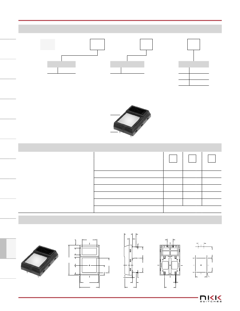
TYPICAL INDICATOR ORDERING EXAMPLE
JF
Shape
01
Terminals
P
C
LED Colors
01
Square
P
Straight PC
C
Red
DESCRIPTION FOR TYPICAL ORDERING EXAMPLE
JF01PC
Red LED
Straight PC Terminals
LED COLORS & SPECIFICATIONS
E
F
Yellow
Green
LED is an integral part of the indicator and
not available separately.
LED polarity markings are on the bottom of
the indicator.
The electrical specifications shown are de-
termined at a basic temperature of 25°C.
If the source voltage exceeds the rated volt-
age, a ballast resistor is required.
The resistor value can be calculated by us-
ing the formula in the Supplement section.
Forward Peak Current
Continuous Forward Current
Forward Voltage
Reverse Peak Voltage
Current Reduction Rate Above 25°C
Ambient Temperature Range
Color
I FM
I F
V F
V RM
?I F
C
Red
30mA
20mA
1.77V
4V
0.4mA/°C
E
Yellow
30mA
20mA
2.1V
4V
0.4mA/°C
–25° ~ +70°C
F
Green
30mA
20mA
2.3V
4V
0.4mA/°C
TYPICAL INDICATOR DIMENSIONS
M
Square
(2.7)
.106
(6.0)
.236
(13.5)
.531
(7.3)
.287
(3.0) Min
.118
(3.0)
.118
(0.5) Sq
.020
(10.16)
.400
–
+
(5.08)
.200
+
–
(5.08)
.200
(10.16)
.400
(26.9) (7.3)
1.059 .287
(8.2)
.323
(13.0) Sq
.512
(8.85)
.348
(12.7)
.500
1
2
3
4
3
4
1
2
(12.7)
.500
(16.4)
.646
(17.7)
.697
(0.3)
.012
(10.3)
.406
(0.3) Typ
.012
(3.6)
.142
(10.16)
.400
(0.8) Typ
.031
(10.16)
.400
(1.0) Dia Typ
.039
JF01PC
M8
www.nkk.com
发布紧急采购,3分钟左右您将得到回复。
相关PDF资料
JN5121-000-M00T
MODULE 802.15.4 W/CERM ANT
JN5139/001,531
MCU 802.15.4 32BIT 2.4G 56-QFN
JN5139-EK000
KIT EVAL IEEE802.15.4 JN5139
JN5139/Z01,515
IC MCU ZIGBEE 32BIT 2.4G 56QFN
JN5139-Z01-M/02R1V
MODULE ZIGBEE SMA CONN HP JN5139
JN5148/001M04T,534
MODULE ZIGBEE PRO HP U.FL CONN
JN5148-UG010
KIT UPGRADE ZIGBEE PRO
K-26-U
TOUCHSCREEN 26" USB
相关代理商/技术参数
JF01PF
功能描述:开关配件 INDICATOR GREEN
RoHS:否 制造商:C&K Components 类型:Cap 用于:Pushbutton Switches 设计目的:
JF040R051040AA
制造商:Japan Aviation Electronics (JAE) 功能描述:
JF0413S1M
制造商:Mallory Sonalert Products Inc 功能描述:
JF04R0R021010AA
制造商:JAE 制造商全称:JAE 功能描述:FFC CONDUCTOR: COPPER ALLOY, INSULATION TAPE: PET / ADHESIVES
JF04R0R021015AA
制造商:JAE 制造商全称:JAE 功能描述:FFC CONDUCTOR: COPPER ALLOY, INSULATION TAPE: PET / ADHESIVES
JF04R0R021020AA
制造商:JAE 制造商全称:JAE 功能描述:FFC CONDUCTOR: COPPER ALLOY, INSULATION TAPE: PET / ADHESIVES
JF04R0R021025AA
制造商:Japan Aviation Electronics (JAE) 功能描述:
JF04R0R021030AA
制造商:JAE 制造商全称:JAE 功能描述:FFC CONDUCTOR: COPPER ALLOY, INSULATION TAPE: PET / ADHESIVES